Building a Working Calculator Inside Figma — From Logic Gates to Binary Addition
- #Figma
- #Digital Logic
- #Computer Architecture
- #Binary Calculator
- #Logic Gates
- #CPU
- #Learning by Building
Building a Working Binary Calculator Inside Figma — My First Step Toward Building a CPU
Figma is a tool I normally associate with designing websites, applications, and user interfaces. It is where we create layouts, buttons, components, and interactive prototypes before implementing them in code.
But what if we could use Figma to do something completely different?
What if we could make it perform actual calculations?
Recently, I came across an interesting project where developers had managed to build an 8-bit CPU inside Figma. Not just a visual representation of a processor, but a functioning digital logic system using Figma's own features.
That immediately caught my attention.
I understood the basic theory of binary numbers and logic gates, but I had never tried to construct a complete computing circuit myself, especially inside a design tool.
I wanted to understand how something like this was possible.
Instead of attempting to recreate an entire CPU immediately, I decided to start with a smaller problem: building a working binary calculator entirely inside Figma.
My goal was not simply to design a calculator interface. I wanted to understand how binary addition works internally, how carry bits move between circuits, and how individual logical operations can be combined into something more useful.
I started with a 1-bit Half Adder, extended it into a Full Adder, connected multiple addition stages to build a 4-bit Ripple Carry Adder, and finally created a normal calculator interface that people could actually use.
The finished calculator accepts two numbers between 0 and 15, calculates their sum using Boolean logic, and displays the result in both decimal and binary.
This post documents the complete process, including the theory, design decisions, Figma variables, prototype interactions, calculations, problems I encountered, and what I learned along the way.
1. Understanding What I Was Trying to Build
Before opening Figma, I needed to understand the actual objective.
A normal calculator application can perform addition with a single line of code.
For example:
const result = 12 + 9;

console.log(result); // 21
There is nothing complicated about that from a programming perspective.
But I wanted to understand what happens at a lower level.
How can a computer add two numbers when its internal circuitry operates using binary signals?
How does it handle a result that cannot fit into a single binary digit?
And how does a larger arithmetic circuit combine smaller calculations into one final answer?
These were the questions I wanted to explore.
My plan was to build the project in several stages:
- Understand how binary addition works.
- Build a 1-bit Half Adder.
- Extend it into a 1-bit Full Adder.
- Connect four addition stages into a 4-bit Ripple Carry Adder.
- Test binary calculations inside Figma.
- Create a normal decimal calculator interface.
- Connect the interface to the existing binary calculation logic.
- Improve the design and user interactions.
- Use the experience as preparation for building more advanced computing circuits.
One important distinction is that I was not building physical electronic components.
I was implementing the logical behavior of digital circuits using Figma's Boolean variables, expressions, and prototype actions.
That distinction matters because Figma is not an electronic circuit simulator. However, its ability to store values and evaluate expressions makes these experiments possible.
2. The Basic Idea Behind Binary Addition
Before building the calculator, I reviewed the fundamentals of binary numbers.
In everyday life, we normally use the decimal number system.
Decimal uses ten digits:
0 1 2 3 4 5 6 7 8 9
Binary uses only two:
0 1
Each binary digit is called a bit.
A bit can represent one of two states, which we can interpret as:
0— False or OFF.1— True or ON.
A four-bit binary number contains four positions.
Each position represents a power of two.
| Bit position | Bit 3 | Bit 2 | Bit 1 | Bit 0 |
|---|---|---|---|---|
| Decimal value | 8 | 4 | 2 | 1 |
For example, binary 0101 represents decimal 5.
Binary:  0 1 0 1
Weight:  8 4 2 1

Calculation:

0 × 8 = 0
1 × 4 = 4
0 × 2 = 0
1 × 1 = 1

Total = 5
Another example is binary 1100.
Binary:  1 1 0 0
Weight:  8 4 2 1

8 + 4 = 12
With four bits, the largest unsigned number we can represent is:
1111 = 15
So a 4-bit calculator can accept numbers from 0 to 15.
However, adding two four-bit numbers can produce an answer larger than 15.
For example:
   1111    (15)
 + 1111    (15)
 -------
  11110    (30)
Notice that the answer contains five bits.
That extra bit is important because it comes from the final carry generated during addition.
This is why my calculator eventually needed four input bits for each number but five output bits for the result.
3. Understanding the Logic Gates Needed for Addition
Binary addition can be constructed using logic gates.
A logic gate receives one or more binary inputs and produces an output according to a particular rule.
For this project, the most important gates were AND, OR, NOT, and XOR.
AND Gate
An AND gate outputs 1 only when both inputs are 1.
| A | B | A AND B |
|---|---|---|
| 0 | 0 | 0 |
| 0 | 1 | 0 |
| 1 | 0 | 0 |
| 1 | 1 | 1 |
Its Boolean expression is:
A and B
OR Gate
An OR gate outputs 1 when at least one input is 1.
| A | B | A OR B |
|---|---|---|
| 0 | 0 | 0 |
| 0 | 1 | 1 |
| 1 | 0 | 1 |
| 1 | 1 | 1 |
Expression:
A or B
NOT Gate
A NOT gate reverses a binary value.
not 0 = 1

not 1 = 0
In Figma, I used NOT expressions to toggle input variables between True and False.
XOR Gate
XOR means Exclusive OR.
It produces 1 when its two inputs are different.
| A | B | A XOR B |
|---|---|---|
| 0 | 0 | 0 |
| 0 | 1 | 1 |
| 1 | 0 | 1 |
| 1 | 1 | 0 |
This is particularly useful for binary addition.
The XOR operation can also be constructed using AND, OR, and NOT:
(A or B) and not (A and B)
I used this expression throughout the project because it allowed me to reproduce XOR behavior using Figma's supported Boolean operators.
Once I understood these gates, I was ready to build the first working circuit.
4. Preparing Figma for the Project
I used Figma Design to create the interface and Figma's prototype functionality to implement the calculations.
The main features I worked with were:
- Frames: To organize the individual circuits and calculator interfaces.
- Shapes and text: To create input buttons, output indicators, and displays.
- Boolean variables: To store individual binary bits.
- Number variables: To store decimal numbers.
- Set variable actions: To change values when buttons are clicked.
- Conditional actions: To perform operations based on logical conditions.
- Variable-bound visibility: To show or hide visual elements based on Boolean values.
- Variable-bound text: To display changing numerical values.
I used a Figma Education plan to access the advanced variable and prototype features needed for the project.
I did not need a separate backend, database, or JavaScript application to execute the calculator.
The calculations run through Figma's native prototype functionality.
Creating the variable collection
One of my first tasks was creating a variable collection called:
BinaryCalculator
This collection eventually contained all the input, output, carry, and display variables used throughout the project.
Keeping them in one collection made it easier to reuse the same variables across different frames.
I started with the simplest circuit possible.
5. Building My First Circuit: The Half Adder
A Half Adder is one of the simplest digital arithmetic circuits.
Its job is to add two individual binary bits.
It has two inputs:
A
B
And two outputs:
SUM
CARRY
Why do we need two outputs?
Consider adding one and one.
In decimal:
1 + 1 = 2
But in binary:
1 + 1 = 10
The answer cannot fit inside a single bit.
So the Half Adder separates the result into a SUM bit and a CARRY bit.
Step 1 — Designing the interface
I created a frame named:
1-Bit Adder
Inside this frame, I designed:
- A button called
Toggle A. - A button called
Toggle B. - A SUM output indicator.
- A CARRY output indicator.
- A CALCULATE button.
For the outputs, I used circles.
A gray circle represented 0, while a green circle represented 1.
At this stage, everything was just a visual design.
The buttons and output indicators had no functionality yet.
Step 2 — Creating the Boolean variables
Inside the BinaryCalculator collection, I created four Boolean variables.
| Variable | Type | Initial value |
|---|---|---|
A |
Boolean | False |
B |
Boolean | False |
SUM |
Boolean | False |
CARRY |
Boolean | False |
These variables allowed the interface to store and modify binary values.
Step 3 — Making the input buttons functional
I selected the Toggle A button and opened:
Prototype → Interactions → On click → Set variable
I configured the action as:
Target: A

Value: not A
This means that every time I click the button, Figma reverses A.
If A is False, it becomes True.
If A is True, it becomes False.
I repeated the same process for Toggle B:
Target: B

Value: not B
Now the two input buttons could independently control their binary values.
Step 4 — Calculating SUM
For the CALCULATE button, I created an On click interaction with a Set variable action.
The target variable was:
SUM
The expression was:
(A or B) and not (A and B)
This reproduces XOR logic.
So when A and B are different, SUM becomes True.
When A and B are equal, SUM becomes False.
Step 5 — Calculating CARRY
I added another Set variable action to the same CALCULATE interaction.
The target was:
CARRY
The expression was:
A and B
This reproduces AND logic.
CARRY becomes True only when both A and B are True.
Step 6 — Connecting variables to the output indicators
I wanted the output circles to change automatically according to the calculated variables.
For each output, I placed a green circle directly above a gray circle.
Then I connected the green circle's visibility to its corresponding Boolean variable.
For example:
SUM_ON visibility → SUM

CARRY_ON visibility → CARRY
When SUM was False, its green circle remained hidden, revealing the gray circle underneath.
When SUM became True, the green circle appeared.
This made it possible to visualize the calculation without changing screens.
Step 7 — Testing the Half Adder
After configuring the interactions, I opened Figma Present mode.
I tested every possible input combination.
| A | B | SUM | CARRY | Binary answer |
|---|---|---|---|---|
| 0 | 0 | 0 | 0 | 00 |
| 0 | 1 | 1 | 0 | 01 |
| 1 | 0 | 1 | 0 | 01 |
| 1 | 1 | 0 | 1 | 10 |
All four combinations worked.
One particularly useful test was:
A = 1
B = 1

SUM = 0
CARRY = 1

Binary answer = 10

Decimal answer = 2
This was my first successful binary addition inside Figma.
The most important thing I learned here was that SUM and CARRY are separate outputs, and both are necessary to represent binary addition correctly.
However, the Half Adder had a limitation.
It could add two bits, but it could not accept a carry from a previous calculation.
To handle that, I needed a Full Adder.
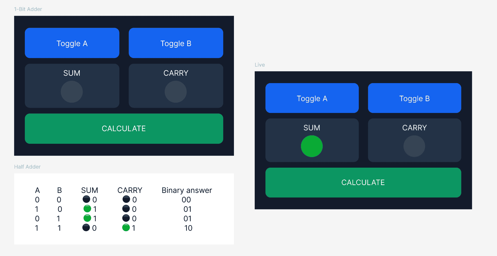
Figure 1: My first working Half Adder in Figma, demonstrating binary addition using XOR and AND logic.
6. Extending the Circuit Into a Full Adder
A Full Adder is an improved version of a Half Adder.
Instead of two inputs, it accepts three:
A
B
CIN
Here, CIN means Carry-in.
Carry-in is the additional bit received from the previous addition stage.
This becomes important when adding numbers containing multiple bits.
Step 1 — Reusing the Half Adder design
Rather than designing everything again, I duplicated the original Half Adder frame.
I renamed the copy:
Full Adder
This allowed me to preserve the working Half Adder while extending its functionality.
Step 2 — Adding Carry-in
I created another Boolean variable:
CIN = False
Then I added a third input button called:
Toggle Cin
Its prototype interaction was:
Target: CIN

Value: not CIN
Now the circuit had three independent binary inputs.
Step 3 — Updating the SUM calculation
A Full Adder calculates SUM using:
SUM = A XOR B XOR CIN
Since I was expressing XOR through AND, OR, and NOT, the actual Figma expression became:
(((A or B) and not (A and B)) or CIN) and not (((A or B) and not (A and B)) and CIN)
This expression performs XOR twice.
First:
A XOR B
Then:
(A XOR B) XOR CIN
The final output is the SUM bit.
Step 4 — Updating the CARRY calculation
The Full Adder's carry-out becomes 1 when at least two of its three inputs are 1.
The expression I used was:
(A and B) or (A and CIN) or (B and CIN)
For example, if A and B are both 1, a carry is produced.
If A and CIN are both 1, a carry is also produced.
The same applies to B and CIN.
Step 5 — Testing the Full Adder
I tested all eight possible combinations.
| A | B | CIN | SUM | CARRY | Binary answer |
|---|---|---|---|---|---|
| 0 | 0 | 0 | 0 | 0 | 00 |
| 0 | 0 | 1 | 1 | 0 | 01 |
| 0 | 1 | 0 | 1 | 0 | 01 |
| 0 | 1 | 1 | 0 | 1 | 10 |
| 1 | 0 | 0 | 1 | 0 | 01 |
| 1 | 0 | 1 | 0 | 1 | 10 |
| 1 | 1 | 0 | 0 | 1 | 10 |
| 1 | 1 | 1 | 1 | 1 | 11 |
One of my favorite tests was:
1 + 1 + 1 = 3
In binary:
1 + 1 + 1 = 11
So both SUM and CARRY become 1.
The circuit produced the expected result.
At this point, I understood how a carry from one addition stage could become an input to another stage.
This was the idea I needed to build a larger adder.
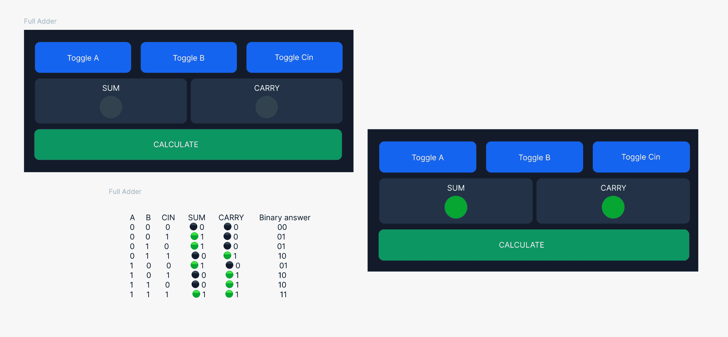
Figure 2: The Full Adder extends the Half Adder by introducing Carry-in (CIN), allowing three binary bits to be added.
7. Building the 4-Bit Ripple Carry Adder
After completing the Full Adder, I moved on to the main arithmetic circuit.
My goal was to add two unsigned 4-bit numbers.
For example:
0101 + 0011 = 01000

5 + 3 = 8
Instead of one Full Adder, the new design required four connected addition stages.
This type of circuit is called a Ripple Carry Adder.
The name comes from the way carry information moves from one stage to the next.
Step 1 — Creating the new frame
I created another Figma frame called:
4-Bit Adder
I wanted a larger workspace because the new design needed more input controls, outputs, and internal variables.
Step 2 — Creating eight input buttons
Each number needs four bits.
So I created four buttons for A:
A3 A2 A1 A0
And four buttons for B:
B3 B2 B1 B0
Each button controlled a Boolean variable with the same name.
For example:
Toggle A3:

Target: A3
Value: not A3
And:
Toggle B0:

Target: B0
Value: not B0
This allowed me to enter any four-bit number manually.
To enter decimal 5:
A3 = 0
A2 = 1
A1 = 0
A0 = 1

A = 0101
To enter decimal 3:
B3 = 0
B2 = 0
B1 = 1
B0 = 1

B = 0011
Step 3 — Creating five output indicators
The result can require five bits, so I created these outputs:
S4 S3 S2 S1 S0
Each output had its own Boolean variable.
| Output | Decimal weight |
|---|---|
S4 |
16 |
S3 |
8 |
S2 |
4 |
S1 |
2 |
S0 |
1 |
Just like the earlier circuits, I used gray and green circles to show whether each output bit was 0 or 1.
The green indicator's visibility was connected to its corresponding output variable.
Step 4 — Creating the internal carry variables
Next, I created three additional Boolean variables:
C1 = False
C2 = False
C3 = False
These variables store the carry between the four addition stages.
Their purpose is:
Bit 0 → C1 → Bit 1

Bit 1 → C2 → Bit 2

Bit 2 → C3 → Bit 3

Bit 3 → S4 (final carry)
I did not create visible buttons for C1, C2, or C3.
They were internal values used by the addition logic.
Step 5 — Understanding the calculation order
The circuit begins with the least significant bit, Bit 0.
That stage calculates:
A0 + B0
It produces:
S0
C1
Then Bit 1 calculates:
A1 + B1 + C1
It produces:
S1
C2
The same process continues through Bit 2 and Bit 3.
In a hardware ripple-carry adder, this behavior is created by connections between combinational logic stages.
In my Figma implementation, I reproduced it using ordered Set variable actions, making sure each carry was updated before the next action used it.
This action order was essential for getting the correct result.
8. Implementing the Four Addition Stages in Figma
I created a CALCULATE button and assigned one On click interaction to it.
Inside that interaction, I added eight Set variable actions.
Each action performed one part of the addition.
Stage 1 — Bit 0
The first stage adds A0 and B0.
It behaves like a Half Adder because the initial carry-in is zero.
Action 1 — Set S0
(A0 or B0) and not (A0 and B0)
Action 2 — Set C1
A0 and B0
These actions produce the first result bit and the carry for the next stage.
Stage 2 — Bit 1
The second stage receives:
A1
B1
C1
Action 3 — Set S1
(((A1 or B1) and not (A1 and B1)) or C1) and not (((A1 or B1) and not (A1 and B1)) and C1)
Action 4 — Set C2
(A1 and B1) or (A1 and C1) or (B1 and C1)
This is the Full Adder logic applied to Bit 1.
Stage 3 — Bit 2
The third stage receives:
A2
B2
C2
Action 5 — Set S2
(((A2 or B2) and not (A2 and B2)) or C2) and not (((A2 or B2) and not (A2 and B2)) and C2)
Action 6 — Set C3
(A2 and B2) or (A2 and C2) or (B2 and C2)
Now the carry is prepared for the final stage.
Stage 4 — Bit 3
The final stage receives:
A3
B3
C3
Action 7 — Set S3
(((A3 or B3) and not (A3 and B3)) or C3) and not (((A3 or B3) and not (A3 and B3)) and C3)
Action 8 — Set S4
(A3 and B3) or (A3 and C3) or (B3 and C3)
Here, S4 stores the final carry-out.
Complete action sequence
| Order | Action | Purpose |
|---|---|---|
| 1 | Set S0 | Calculate Bit 0 SUM |
| 2 | Set C1 | Carry from Bit 0 |
| 3 | Set S1 | Calculate Bit 1 SUM |
| 4 | Set C2 | Carry from Bit 1 |
| 5 | Set S2 | Calculate Bit 2 SUM |
| 6 | Set C3 | Carry from Bit 2 |
| 7 | Set S3 | Calculate Bit 3 SUM |
| 8 | Set S4 | Final carry |
All eight actions belonged to the same CALCULATE interaction.
I was not writing the formulas inside a JavaScript program. I entered the expressions using Figma's variable expression editor, selecting the actual variables from the variable picker.
This was the calculation engine of my project.
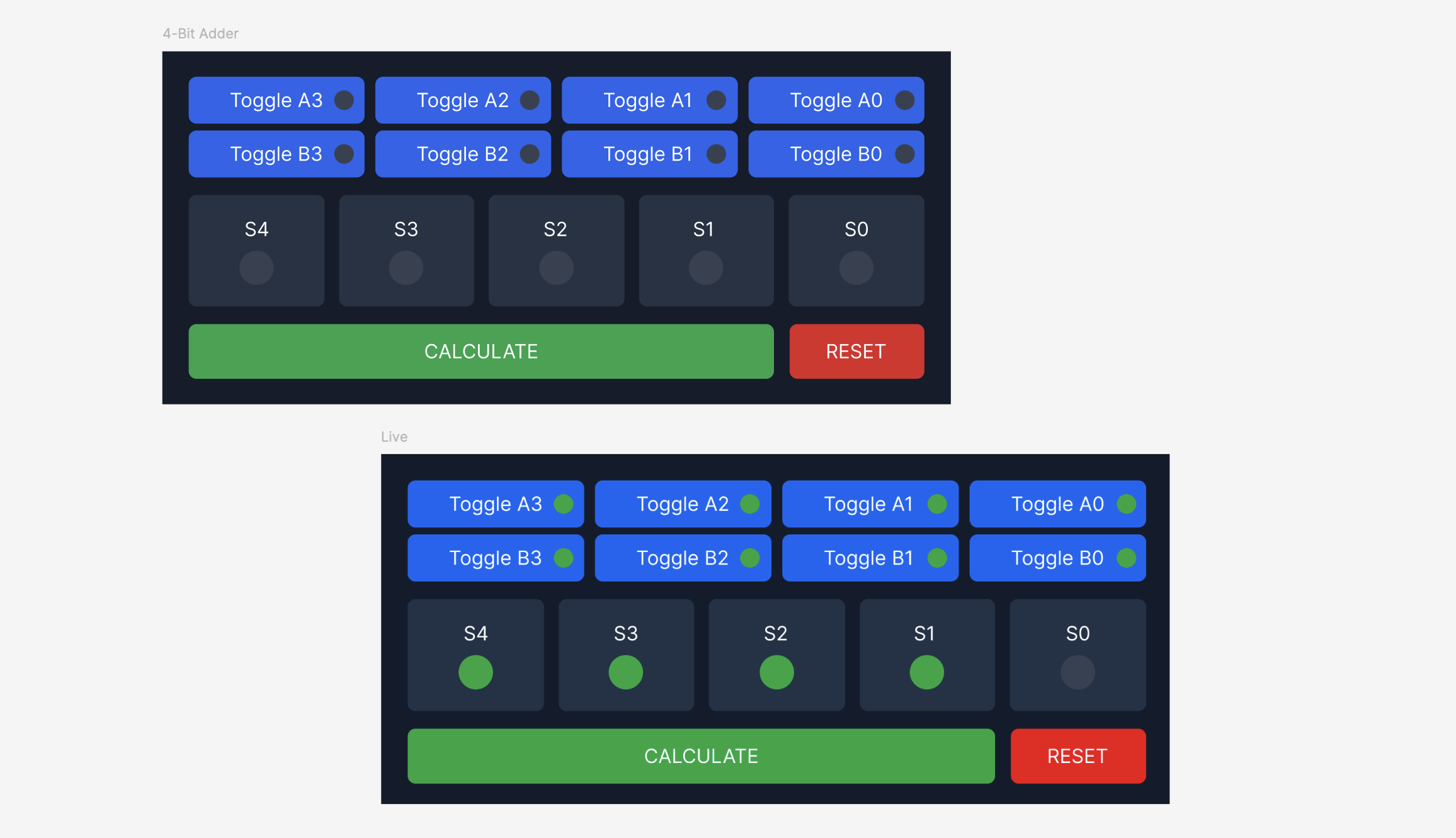
Figure 3: My 4-bit Ripple Carry Adder, combining four addition stages with carry propagation to calculate results up to 30.
9. Testing the 4-Bit Calculator
Before creating a normal calculator interface, I wanted to make sure the underlying addition logic worked correctly.
I opened Figma Present mode and tested different binary input combinations.
Test 1 — Adding 5 and 3
The inputs were:
A = 0101
B = 0011
Expected result:
  0101
+ 0011
------
  1000
With the fifth output bit included:
01000
Decimal result:
5 + 3 = 8
The output indicators showed the expected value.
Only S3 was 1.
Test 2 — Adding 7 and 1
This test was especially interesting because it demonstrated carry propagation.
A = 0111
B = 0001
Binary addition:
  0111
+ 0001
------
  1000
What happens internally?
- Bit 0 adds 1 + 1 and generates a carry.
- Bit 1 adds 1 + 0 + 1 and generates another carry.
- Bit 2 adds 1 + 0 + 1 and generates another carry.
- Bit 3 receives that carry and produces 1.
The result becomes:
01000 = 8
This helped me understand why the stages need to be connected correctly.
Test 3 — Adding 15 and 15
I also tested the maximum possible inputs.
A = 1111
B = 1111
The expected result was:
11110
Which represents:
15 + 15 = 30
The first four output indicators turned green while S0 remained gray.
This confirmed that the final carry bit was being handled correctly.
Adding a RESET button
I later added a RESET button to clear the input and output state.
It used multiple Set variable actions to reset:
- All eight input bits.
- All five output bits.
- The three internal carry variables.
Every variable was set to False.
I tested the calculator again after resetting it and confirmed that it could perform another addition successfully.
At this point, the actual 4-bit binary adder was complete.
But the interface was still designed for someone who understood binary numbers.
I wanted to make it easier for anyone to use.
10. Turning the Binary Circuit Into a Normal Calculator
The original 4-bit adder worked, but entering numbers was not convenient.
If someone wanted to calculate 5 + 3, they needed to understand that:
5 = 0101

3 = 0011
Then they had to turn on the corresponding input bits.
That was useful for learning, but not ideal for a public demonstration.
I wanted people to open the calculator, press normal number buttons, and see the result immediately.
So I decided to build a separate interface around the existing calculation logic.
Step 1 — Duplicating the existing calculator
I duplicated my working 4-bit Adder frame.
I renamed the new frame:
BinaryCalc - Showcase
The original frame remained untouched.
This was important because I wanted to preserve the circuit interface as a separate learning demonstration.
Step 2 — Creating the digital display
Inside the new frame, I designed a display containing three main areas.
Calculation history
12 + 9
Decimal result
21
Binary result
10101
The display initially contained placeholder values.
Later, I connected those values to Figma variables.
Step 3 — Building the number keypad
I created a normal keypad containing:
7    8    9    DEL

4    5    6     +

1    2    3     =

   RESET     0
The keypad was initially just a visual design.
Each button needed its own prototype interaction before it could work.
My next challenge was to make the interface remember decimal numbers.
11. Making the Calculator Accept Decimal Numbers
The binary adder worked with Boolean variables, but a normal keypad needed Number variables.
I created a new variable:
Entry = 0
Its type was Number.
I connected Entry to the large numerical display using Figma's variable binding for text content.
Now whenever Entry changed, the visible display changed automatically.
Step 1 — Making the number buttons functional
For my first experiment, I configured the 7 button to perform:
Set Entry = 7
Clicking the button changed the display to 7.
However, this only worked for single-digit entry.
If I pressed 1 and then 5, I wanted the display to show 15.
Setting the variable directly to each digit would not achieve that.
Step 2 — Supporting multi-digit entry
I changed the input logic to:
Entry * 10 + digit
For example, when Entry is 1 and the user presses 5:
1 * 10 + 5 = 15
This is how the keypad can build multi-digit numbers.
However, the binary calculation engine only supports inputs between 0 and 15.
So I added a condition to prevent invalid inputs.
For the 7 button, the condition was:
Entry * 10 + 7 <= 15
Inside the IF branch, I added:
Set Entry = Entry * 10 + 7
The ELSE branch was left empty.
This means the button updates Entry only when the resulting number is within the supported range.
I repeated the same logic for all ten number buttons.
For example:
| Button | Condition | Update |
|---|---|---|
| 1 | Entry * 10 + 1 <= 15 |
Entry * 10 + 1 |
| 2 | Entry * 10 + 2 <= 15 |
Entry * 10 + 2 |
| 5 | Entry * 10 + 5 <= 15 |
Entry * 10 + 5 |
| 9 | Entry * 10 + 9 <= 15 |
Entry * 10 + 9 |
This allowed me to enter numbers naturally using the keypad.
Fixing a display problem
While testing multi-digit entry, I encountered a visual issue.
The display showed 7 correctly, but when it changed to 15, part of the text moved outside the display boundary.
The problem was not related to the calculation.
It was caused by the text layer's resizing behavior.
I fixed it by:
- Selecting the display's text layer.
- Changing the text resizing mode to Auto height.
- Giving the text box a fixed width.
- Aligning its text to the right.
- Positioning the text box inside the display with enough padding.
After that, the display could show one-digit and two-digit numbers without overflowing.
This reminded me that even when the underlying logic works, the interface still needs careful attention.
12. Storing Two Numbers for Addition
The next challenge was allowing someone to enter two separate numbers.
For example:
12 + 9 =
The calculator needed to remember 12 while the user entered 9.
To handle this, I created two more Number variables:
FirstNumber = 0

SecondNumber = 0
Now I had three main numeric variables.
| Variable | Purpose |
|---|---|
Entry |
Number currently displayed or entered |
FirstNumber |
First operand |
SecondNumber |
Second operand |
Configuring the + button
When someone presses the plus button, the calculator needs to:
- Save the current Entry as the first number.
- Prepare the display for the next number.
My initial interaction contained:
Set FirstNumber = Entry

Set Entry = 0
Later, I improved it to clear the previous second number and manage the calculation state.
Configuring the = button
When someone presses equals, Figma needs to save the second operand.
The first action was:
Set SecondNumber = Entry
For example:
User presses: 1, 2

Entry = 12
Then:
User presses: +

FirstNumber = 12
Entry = 0
Then:
User presses: 9

Entry = 9
Finally:
User presses: =

SecondNumber = 9
Now both operands are stored.
But there was still a major problem.
My arithmetic circuit expected binary inputs, not decimal Number variables.
I needed to connect these two systems.
13. Converting Decimal Inputs Into Binary Variables
This was one of the most interesting parts of the project.
I had two systems:
The user interface, which stored decimal numbers.
FirstNumber = 12

SecondNumber = 9
The binary calculation engine, which expected individual Boolean bits.
A3 A2 A1 A0

B3 B2 B1 B0
To connect them, I needed to convert the stored decimal values into binary.
Converting FirstNumber
For example:
FirstNumber = 12

Binary = 1100
That means:
A3 = 1
A2 = 1
A1 = 0
A0 = 0
I added four Set variable actions to the equals button.
Each action checked whether a particular binary bit should be True or False.
A3 — The 8's place
FirstNumber >= 8
If FirstNumber is 8 or greater, A3 becomes True.
A2 — The 4's place
((FirstNumber >= 4) and (FirstNumber < 8)) or (FirstNumber >= 12)
This makes A2 True for numbers 4–7 and 12–15.
A1 — The 2's place
((FirstNumber >= 2) and (FirstNumber < 4)) or ((FirstNumber >= 6) and (FirstNumber < 8)) or ((FirstNumber >= 10) and (FirstNumber < 12)) or (FirstNumber >= 14)
This makes A1 True for numbers:
2, 3, 6, 7, 10, 11, 14, 15
A0 — The 1's place
(FirstNumber == 1) or (FirstNumber == 3) or (FirstNumber == 5) or (FirstNumber == 7) or (FirstNumber == 9) or (FirstNumber == 11) or (FirstNumber == 13) or (FirstNumber == 15)
This makes A0 True whenever FirstNumber is odd.
These four actions convert any supported FirstNumber into its corresponding binary bits.
Converting SecondNumber
I repeated the same process for the B variables.
B3
SecondNumber >= 8
B2
((SecondNumber >= 4) and (SecondNumber < 8)) or (SecondNumber >= 12)
B1
((SecondNumber >= 2) and (SecondNumber < 4)) or ((SecondNumber >= 6) and (SecondNumber < 8)) or ((SecondNumber >= 10) and (SecondNumber < 12)) or (SecondNumber >= 14)
B0
(SecondNumber == 1) or (SecondNumber == 3) or (SecondNumber == 5) or (SecondNumber == 7) or (SecondNumber == 9) or (SecondNumber == 11) or (SecondNumber == 13) or (SecondNumber == 15)
The equals button now prepared both binary operands.
Example: 12 + 9
The conversion produced:
FirstNumber = 12

A3 = 1
A2 = 1
A1 = 0
A0 = 0

A = 1100
And:
SecondNumber = 9

B3 = 1
B2 = 0
B1 = 0
B0 = 1

B = 1001
Now the decimal interface could provide inputs to my existing Boolean arithmetic logic.
I did not replace the adder with a direct numeric addition expression. The keypad prepared binary inputs that the adder logic could process.
14. Connecting the Decimal Calculator to the Binary Adder
After converting both operands, I needed to perform the actual addition.
Fortunately, I had already built the complete logic for the 4-bit adder.
I reused those expressions inside the equals button's existing On click interaction.
The important detail was the action sequence.
First, Figma stored the second decimal number.
Next, it converted both operands into their binary bits.
Then, it performed the addition stage by stage.
The calculation sequence was:
| Order | Action |
|---|---|
| 1 | Store SecondNumber |
| 2 | Convert A3 |
| 3 | Convert A2 |
| 4 | Convert A1 |
| 5 | Convert A0 |
| 6 | Convert B3 |
| 7 | Convert B2 |
| 8 | Convert B1 |
| 9 | Convert B0 |
| 10 | Calculate S0 |
| 11 | Calculate C1 |
| 12 | Calculate S1 |
| 13 | Calculate C2 |
| 14 | Calculate S2 |
| 15 | Calculate C3 |
| 16 | Calculate S3 |
| 17 | Calculate S4 |
The same eight Boolean calculations from my original adder were used again.
The carry actions had to come before the stages that depended on them.
For example:
Calculate C1

Then calculate S1 using C1
If I changed the order, the next stage could use an old carry value instead of the value produced by the current calculation.
After implementing this sequence, the equals button could execute the complete binary addition.
But I still needed to display the result as a decimal number.
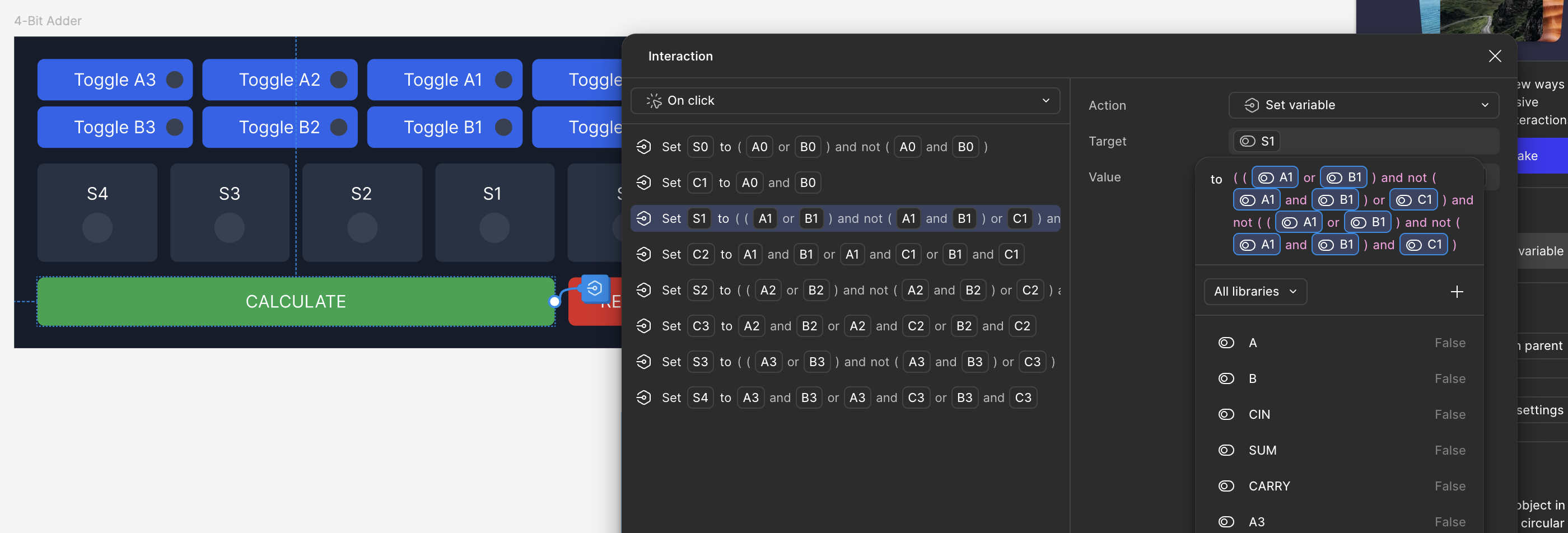
Figure 4: Implementation of the 4-bit Ripple Carry Adder using Figma's native prototype interactions. The eight actions calculate each sum bit and propagate carry values between stages, while the selected S1 action shows the underlying Boolean expression.
15. Converting the Binary Result Back Into Decimal
After the four addition stages, the result was stored in five Boolean variables.
For example, adding 12 and 9 produced:
S4 S3 S2 S1 S0

 1  0  1  0  1
Which is:
10101
This represents decimal 21.
To show that number in the main display, I needed to convert the binary result back into decimal.
Each output bit has a corresponding decimal weight.
| Variable | Decimal value |
|---|---|
| S4 | 16 |
| S3 | 8 |
| S2 | 4 |
| S1 | 2 |
| S0 | 1 |
The idea was simple.
Start the display value at zero.
Then add the value of every output bit that is True.
Step 1 — Reset the display value
After the binary calculation actions, I added:
Set Entry = 0
Step 2 — Read S4
I created a Conditional action.
IF S4
Inside the IF branch:
Set Entry = Entry + 16
Step 3 — Read S3
I added another independent Conditional action.
IF S3
Inside the IF branch:
Set Entry = Entry + 8
Step 4 — Read S2
IF S2

Set Entry = Entry + 4
Step 5 — Read S1
IF S1

Set Entry = Entry + 2
Step 6 — Read S0
IF S0

Set Entry = Entry + 1
All five conditions were separate.
I did not nest them inside one another because every bit needs to be checked independently.
Example: Converting 10101 into decimal
For the binary result:
10101
The process becomes:
Entry = 0

S4 = 1 → Entry = 0 + 16 = 16

S3 = 0 → No change

S2 = 1 → Entry = 16 + 4 = 20

S1 = 0 → No change

S0 = 1 → Entry = 20 + 1 = 21
Final result:
Entry = 21
Since the large white display was already connected to Entry, it automatically showed 21.
This completed the connection between the decimal keypad, binary adder, and decimal result display.
The calculation flow was now:
Decimal keypad
      |
      v
Store FirstNumber and SecondNumber
      |
      v
Convert decimal numbers into binary bits
      |
      v
Execute the 4-bit addition logic
      |
      v
Generate S4, S3, S2, S1, S0
      |
      v
Convert the binary result into decimal
      |
      v
Display the answer
This was the most important part of the entire project.
16. Making the Calculation and Binary Displays Dynamic
The calculation engine was working, but the showcase still contained some placeholder text.
For example, the calculation line originally displayed:
0
+
0
Even after calculating a different expression.
I wanted the interface to show the actual numbers entered by the user.
Connecting the calculation history
I replaced the static calculation text with three separate text layers:
0
+
0
I connected the first number to:
FirstNumber
And the second number to:
SecondNumber
The plus sign remained ordinary text.
Now the history updated automatically.
For example:
12 + 9
Making the binary result dynamic
I also wanted the interface to display the actual binary answer.
Initially, the display contained static text:
00000
But each binary digit needed to change independently.
So I replaced that text with five separate digit positions.
For each position, I created:
- A gray
0text layer. - A green
1text layer. - A Boolean visibility binding.
The bindings were:
| Binary digit | Visibility variable |
|---|---|
| BIT4_ON | S4 |
| BIT3_ON | S3 |
| BIT2_ON | S2 |
| BIT1_ON | S1 |
| BIT0_ON | S0 |
When a particular output bit became True, its green digit appeared.
Fixing the overlapping digit problem
I encountered another interface issue while implementing this.
I initially placed the green 1 directly on top of the gray 0.
However, both characters remained partially visible.
This happened because text layers have transparent backgrounds.
Simply placing a 1 above a 0 does not completely hide the original digit.
To solve the problem, I used a small opaque background behind each green 1.
The layer arrangement became:
Green 1
Opaque background
Gray 0
I grouped the green digit with its background and connected the group's visibility to the corresponding output variable.
When the variable was False, the group remained hidden.
When it became True, the background covered the gray digit and the green 1 appeared cleanly.
This fixed the overlapping issue.
After that, the calculator could display results such as:
12 + 9 = 21

Binary: 10101
Everything was updated through the actual Figma variables.
17. Implementing RESET, DEL, and Repeated Calculations
I did not want the project to be just a technical demonstration.
I wanted it to behave reasonably well when someone else tried using it.
That meant adding some basic calculator controls.
Implementing RESET
I created a RESET button that cleared the complete calculation state.
It needed to reset more than just the visible display.
The calculator stored data in multiple types of variables.
Decimal variables
Entry = 0

FirstNumber = 0

SecondNumber = 0
Binary input variables
A3 = False
A2 = False
A1 = False
A0 = False

B3 = False
B2 = False
B1 = False
B0 = False
Binary output variables
S4 = False
S3 = False
S2 = False
S1 = False
S0 = False
Internal carry variables
C1 = False
C2 = False
C3 = False
I added Set variable actions for each of these values inside the RESET button's On click interaction.
This ensured that RESET cleared both the visible interface and the stored arithmetic state.
Implementing DEL
I also wanted a button that could delete the last displayed digit.
For example:
15 → 1 → 0
Since the displayed values were limited to whole numbers from 0 to 30, I implemented DEL using conditional ranges.
| Condition | New Entry |
|---|---|
Entry < 10 |
0 |
Entry >= 10 and Entry < 20 |
1 |
Entry >= 20 and Entry < 30 |
2 |
Entry >= 30 |
3 |
Each condition updated Entry to the corresponding remaining digit.
This was a simple approach suited to the limited number range of the project.
It was not intended to be a general-purpose text-editing system.
Handling a completed calculation
Another problem appeared after pressing equals.
Suppose the calculator showed:
12 + 9 = 21
What should happen if someone presses 5 immediately afterward?
I wanted the calculator to begin a fresh number rather than attempt to append 5 to 21.
To handle this, I created another Boolean variable:
ResultShown = False
When equals completed a calculation, I set:
ResultShown = True
When RESET was pressed, I set:
ResultShown = False
Then I updated the number buttons to check whether a previous result was being displayed.
For example, the 7 button used three actions.
First condition
(not ResultShown) and (Entry * 10 + 7 <= 15)
Inside IF:
Set Entry = Entry * 10 + 7
Second condition
IF ResultShown
Inside IF:
Set Entry = 7
Final action
Set ResultShown = False
I repeated this pattern for the remaining digit buttons.
This allowed the calculator to start a new entry after showing a result.
Supporting chained addition
I also wanted to perform consecutive additions without pressing RESET between them.
For example:
5 + 3 = 8

8 + 4 = 12
I updated the plus button to reuse the displayed result when it was within the valid four-bit input range.
The condition was:
Entry <= 15
Inside the IF branch, the actions were:
Set FirstNumber = Entry

Set SecondNumber = 0

Set Entry = 0

Set ResultShown = False
This stored the previous result as the first operand of the next calculation.
If the displayed value was greater than 15, I prevented it from being reused as a four-bit input.
That was necessary because the underlying arithmetic circuit still accepted only four-bit operands.
After testing, chained addition worked.
For example:
5 + 3 = 8

8 + 4 = 12
The final binary result was:
01100
This made the calculator more convenient to demonstrate.
18. Designing the Final BinaryCalc Interface
Once the functionality was complete, I focused on the visual presentation.
The original calculator showed eight binary toggle buttons and five output indicators.
It was useful for learning, but I wanted the finished project to look like an actual application.
I kept the original binary interface as a separate circuit demonstration and hid the duplicate debugging controls from the showcase.
The final layout contained:
- BinaryCalc branding.
- A 4-BIT ENGINE label.
- A digital calculation display.
- A large decimal result.
- A five-bit binary result.
- A normal number keypad.
- DEL, RESET, +, and = buttons.
- A short explanation of the underlying calculation logic.
Choosing the visual style
For the final design, I wanted something different from the dark interface I originally created.
I took inspiration from the bold, comic-book-inspired styling of jubayer.host.
The visual direction used a warm background, strong contrast, colorful controls, and clear typography.
Some of the colors I worked with were:
| Element | Color |
|---|---|
| Main background | #FFFAEB |
| Dark text and outlines | #15141C |
| Yellow accent | #FFDA4D |
| Red accent | #F24E54 |
| Blue accent | #344BD0 |
| Light panels | #FFFFFF |
| Secondary text | #595662 |
I also used stronger borders, smaller corner radii, and a more expressive visual style.
The purpose of the redesign was not to make the calculator more complicated.
I wanted someone to immediately understand that it was a calculator, while still recognizing that the project was related to binary computing.
Adding the technical description
At the bottom of the interface, I included:
Powered by Binary Logic
Built entirely in Figma using a 4-bit ripple-carry adder.
Addition: 0–15 + 0–15
Output: 0–30
This short description explains the project's main technical idea without requiring someone to study the full circuit first.
I also organized the interface into groups so I could move and resize the layout without accidentally changing individual buttons or their interactions.
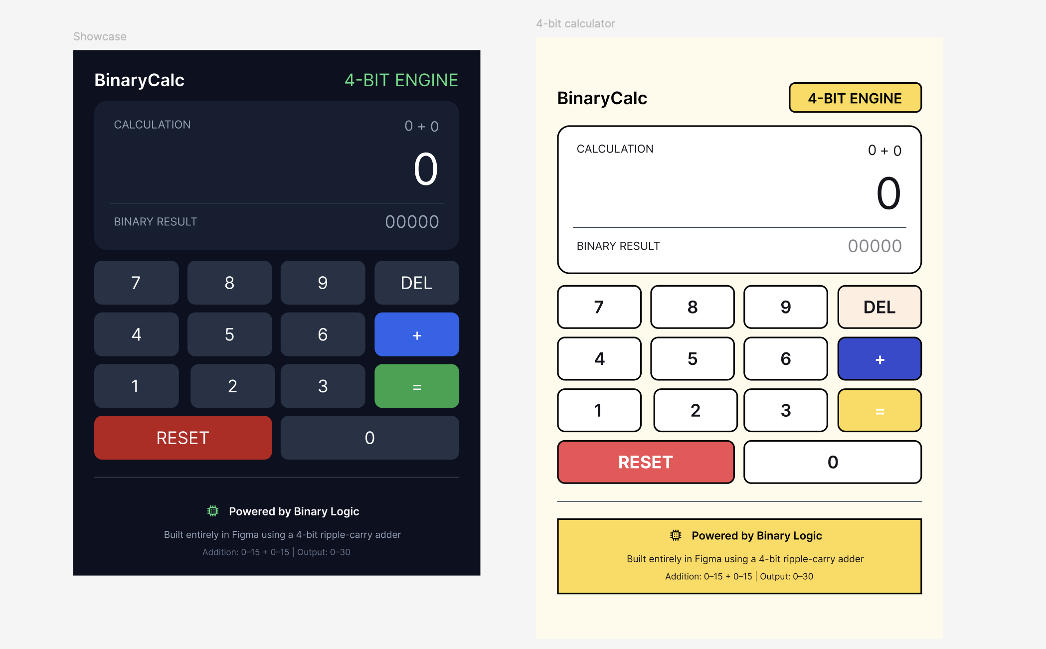
Figure 5: The finished BinaryCalc interface, featuring a decimal keypad, calculation history, binary result display, and interactive controls.
19. Final Testing and Results
After completing the interface and prototype interactions, I tested the calculator again.
I wanted to make sure the normal keypad still produced results through the binary calculation logic.
Test results
| Calculation | Expected decimal | Expected binary | Result |
|---|---|---|---|
| 5 + 3 | 8 | 01000 | Passed |
| 7 + 1 | 8 | 01000 | Passed |
| 10 + 5 | 15 | 01111 | Passed |
| 10 + 6 | 16 | 10000 | Passed |
| 12 + 9 | 21 | 10101 | Passed |
| 15 + 15 | 30 | 11110 | Passed |
| 3 + 4 | 7 | 00111 | Passed |
I also checked several interface interactions.
RESET
The calculator cleared the decimal values, binary outputs, input bits, and carry variables.
DEL
Deleting a two-digit number changed it to the remaining first digit.
For example:
15 → 1 → 0
New calculation after equals
After completing a calculation, pressing a digit started a fresh entry.
Chained addition
I tested:
5 + 3 = 8

Then:

8 + 4 = 12
The calculator produced the correct result without requiring a full reset.
These tests helped me confirm that the core addition logic and the main user interactions were working in the cases I checked.
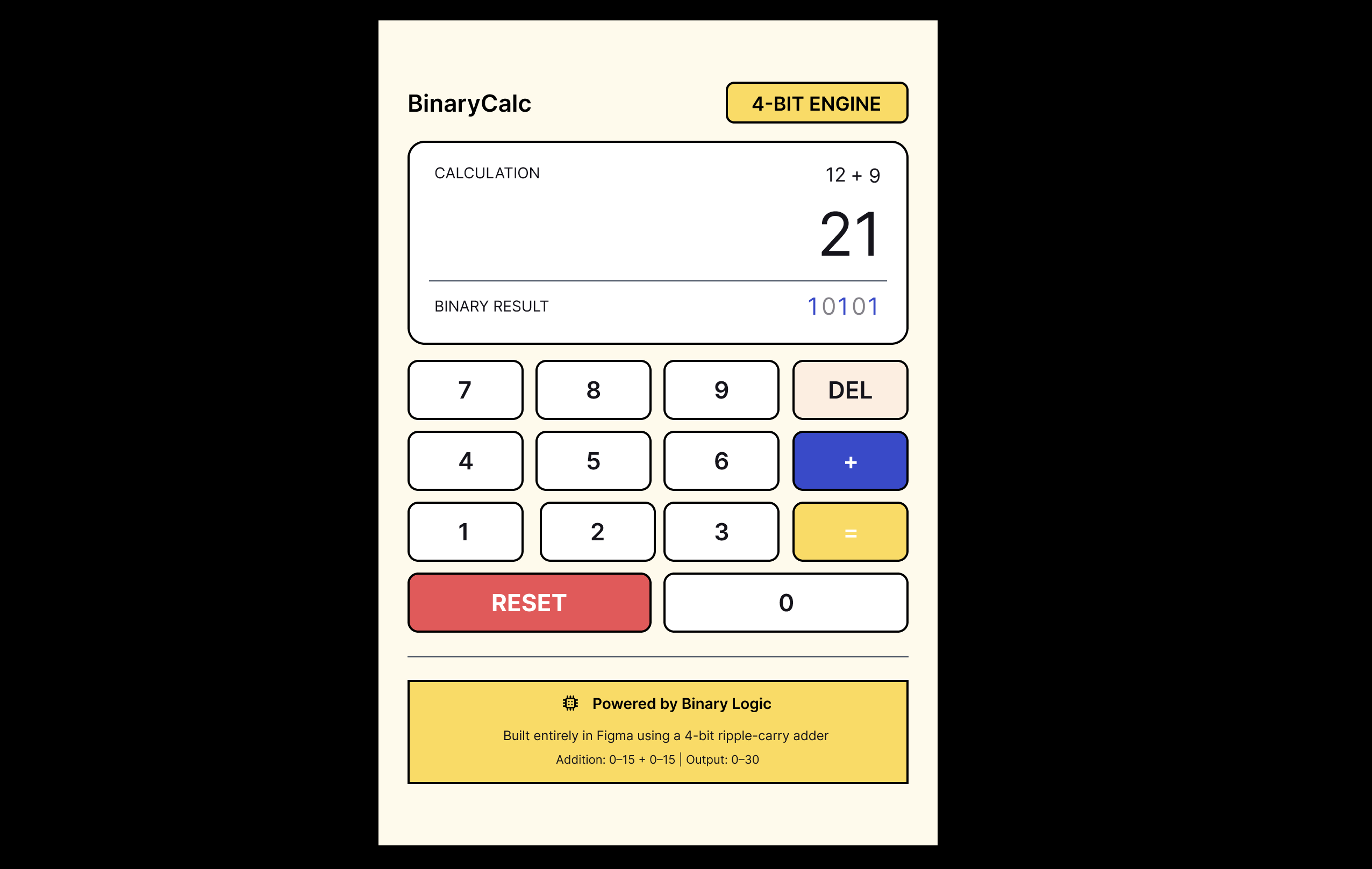
Figure 6: A successful calculation of 12 + 9 = 21 in Figma Present mode. The calculator displays both the decimal result and its five-bit binary representation, generated using the 4-bit Ripple Carry Adder logic.
20. Problems I Encountered and How I Solved Them
Although the idea sounds simple, there were several practical challenges.
Some were related to Boolean logic, while others came from Figma's layout and prototype system.
Problem 1 — Understanding how to represent logic gates
Initially, I knew what AND, OR, and XOR gates did, but I did not know how to implement them inside Figma.
The solution was to treat Boolean variables as digital signals and use Figma expressions to reproduce the required gate behavior.
For example:
A and B
Represents AND.
And:
(A or B) and not (A and B)
Represents XOR.
This became the foundation of the project.
Problem 2 — Managing carry propagation
The 4-bit adder depended on internal carry variables.
If one stage used a carry value before it was updated, the calculation could become incorrect.
I addressed this by keeping the addition actions in the correct order.
Each stage calculated its carry before the next stage used that value.
Problem 3 — Entering decimal numbers
The original calculator required users to select binary bits manually.
That made the interface difficult for people unfamiliar with binary numbers.
I solved this by creating a normal keypad and converting the decimal values into Boolean input bits before performing the addition.
Problem 4 — Keeping input values within the supported range
A four-bit operand can represent only 0 to 15.
Without input restrictions, the keypad could accept unsupported values.
I used conditional actions to prevent multi-digit entries from exceeding 15.
I also prevented answers greater than 15 from being reused directly as four-bit operands in chained calculations.
Problem 5 — Text overflowing the display
When the display changed from one digit to two digits, the text extended beyond the panel.
I fixed the text box width and alignment so the display could grow without changing its position unexpectedly.
Problem 6 — Overlapping binary digits
Placing a green 1 directly above a gray 0 did not hide the zero because both text layers were transparent.
I fixed this by placing an opaque background behind the green digit and controlling the group's visibility through a Boolean variable.
Problem 7 — Resetting all the stored values
The calculator stored more information than the visible decimal result.
Resetting only the display would leave the binary inputs and internal carries unchanged.
I created a complete RESET interaction that cleared every relevant variable.
Problem 8 — Making the calculator usable after an answer
Initially, the interface did not know whether the displayed number was a new input or a completed result.
The ResultShown Boolean variable allowed me to distinguish those situations.
This improved the behavior of the number buttons and chained addition.
These problems taught me that building a working logical system and building a usable interface are two different challenges. Both matter.
21. What the Calculator Can and Cannot Do
I also want to be clear about the project's technical scope.
The calculator is a working 4-bit unsigned binary addition system implemented inside Figma.
It supports two decimal operands from 0 to 15 and produces a five-bit result from 0 to 30.
The calculation is performed through Boolean addition expressions and carry variables.
However, this is not a complete general-purpose calculator.
At its current stage, it does not implement:
- Subtraction.
- Multiplication.
- Division.
- Floating-point arithmetic.
- Arbitrarily large numbers.
- A general-purpose instruction set.
- A clock-driven CPU architecture.
Also, the logical gates are expressed through Figma's built-in operators rather than constructed from physical transistors.
The four arithmetic stages are implemented as ordered prototype actions.
This makes the project a useful digital logic demonstration, but it is not equivalent to manufacturing a processor or building a transistor-level electronic circuit.
I think that distinction is important.
My objective was to understand and reproduce the behavior of binary arithmetic, not to claim that Figma had become a physical computer chip.
And for that learning objective, the project was valuable.
22. What I Learned From Building BinaryCalc
Before starting this project, I understood binary numbers and basic logic gates mostly as theoretical concepts.
I knew what an XOR gate did.
I knew that computers use binary.
And I had studied the general idea of computer architecture.
But implementing the logic myself helped me understand how these concepts connect.
First, I learned how basic gates form arithmetic circuits.
A Half Adder uses XOR and AND logic to produce SUM and CARRY.
A Full Adder extends that behavior by accepting Carry-in.
Second, I learned how larger arithmetic circuits are constructed from smaller stages.
The 4-bit Ripple Carry Adder does not perform one mysterious operation.
It performs several smaller additions, with carry information passed between stages.
Third, I understood why the order of operations matters in my Figma implementation.
Each carry had to be available before the next stage used it.
Fourth, I learned how to represent binary data using variables.
Boolean variables worked as the binary inputs, outputs, and internal carry signals of the circuit.
Fifth, I learned how to connect two different representations of the same information.
The user entered decimal numbers, but the arithmetic logic used binary inputs.
Converting between those representations made the calculator usable without changing the core binary calculation method.
Finally, I learned that building the interface is not separate from understanding the system.
The keypad, display, input validation, reset behavior, and dynamic binary output all helped make the underlying logic easier to demonstrate and understand.
The finished project may look like a small calculator, but the process introduced me to several ideas that also appear in much larger computing systems.
23. My Next Goal: From Calculator to CPU
This calculator is not the final objective.
It is my starting point.
The original project that inspired me demonstrated that complex digital logic systems could be implemented inside Figma.
I want to continue exploring that idea, but I also want to understand the architecture rather than simply reproduce someone else's design.
My next goal is to build a small Arithmetic Logic Unit, commonly called an ALU.
An ALU is one of the important components inside a CPU.
Unlike my current adder, an ALU can perform different types of operations depending on the control signals it receives.
For example:
Operation 00 → ADD

Operation 01 → SUBTRACT

Operation 10 → AND

Operation 11 → OR
These are examples of the operations I want to explore in a future 4-bit ALU.
After that, I want to learn how to build:
- Multiplexers: Circuits that select between different inputs.
- Registers: Circuits that store binary values.
- Clocked logic: Systems that update their state at controlled intervals.
- Program counters: Components that track the next instruction.
- Memory: A place to store data and instructions.
- Control units: Logic that decides which operations happen and when.
- Instruction execution: The Fetch–Decode–Execute process used by processors.
Eventually, I want to combine these ideas into a small CPU inside Figma.
I know this will be considerably more challenging than building a calculator.
But that is part of why I started with this project.
Rather than jumping straight to a complete CPU, I want to understand the smaller components first and gradually connect them into a larger working system.
24. Final Thoughts
When I first saw someone build a CPU inside Figma, I found it difficult to imagine how a design tool could be used for something like that.
Now, after building my own binary calculator, I understand the basic idea much better.
Figma's variables and prototype interactions can be used to represent binary states, evaluate logical expressions, update intermediate values, and display the results.
By combining those features, I was able to implement a Half Adder, Full Adder, and 4-bit Ripple Carry Adder before turning the system into an interactive calculator.
The most valuable part of the project was not getting the correct answer to a calculation.
It was understanding how that answer could be produced from smaller logical operations.
I started with:
1 + 1 = 10
Then progressed to:
Half Adder
    |
    v
Full Adder
    |
    v
4-Bit Ripple Carry Adder
    |
    v
Decimal Input and Output
    |
    v
Working Calculator in Figma
And this is only the first stage of what I want to build.
Next, I plan to explore ALUs, registers, memory, and the logic required for instruction execution.
One circuit at a time, I want to work toward building my own CPU inside Figma.
Project Links and Resources
Live calculator: Try BinaryCalc in Figma
Original inspiration: 8-bit CPU built inside Figma
Next project: Building a 4-bit Arithmetic Logic Unit inside Figma.
BinaryCalc — Project 01 of my journey toward building a CPU.